chiller Air-Cooled Condensers operation and maintenance
Troubleshooting Chart
Troubleshooting Chart
 |
| air cooled condensers |
Introduction
Carefully check each shipment against the bill of lading and account for all items. Report any shortage or damage to the delivering carrier.
On receipt of equipment, check the unit nameplate for correct electrical characteristics and working pressure. Refrigerants R-22, R-134a, R-407c have 450 psi; R-410A has 650 psi.
Be careful to prevent damage when uncrating. Heavy equipment should be left on unit’s shipping base until it has been moved to the final location.
This equipment must be installed in accordance with accepted industry standards. Failure to meet the following conditions may void the warranty:
1. System piping must be installed following industry standards for good piping practices.
2. Inert gas must be charged into piping during brazing/welding.
3. System must be thoroughly leak-checked and evacuated before initial charging. High vacuum gauge capable of reading microns is mandatory. Dial indicating pressure gauges are not acceptable.
4. Power supply to system must meet the following conditions:
Voltage for 208/230 motors not less than 195 volts or more than 253 volts.
All other voltages must be within 10% of nameplate ratings.
Phase imbalance not to exceed 2%.
5. All controls and safety switch circuits properly connected per wiring diagram.
6. Factory installed wiring must not be changed without written factory approval.
7. Relief valves must meet all code requirements.
Refrigerant Piping:
<
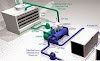
illustrates a typical piping arrangement involving a remote condenser located at a higher elevation, as commonly encountered when the condenser is on a roof and the compressor and receiver are on grade level or in a basement equipment room. In this case, the design of the discharge line is very critical. If properly sized for full load condition, the gas velocity might be too low at reduced loads to carry oil up through the discharge line and condenser coil. Reducing the discharge line size would increase the gas velocity sufficiently at reduced load conditions; however, when operating at full load, the line would be greatly undersized, and thereby create an excessive refrigerant pressure drop. This condition can be overcome in one of the two following ways:
1. Size discharge line for the desired pressure drop at full load conditions and install an oil separator at the bottom of the trap in the discharge line from the compressor.
2. Use a double riser discharge line as shown in Figure 2. Size line "A" to carry the oil at minimum load conditions and size line "B" at full load conditions; both lines should have sufficient flow velocity to carry the oil to the condenser.
For more complete information, see the ASHRAE Handbook on Systems.
Be aware of the following when fabricating piping:
• All oil traps are to be as short in radius as possible. The trap may be fabricated using three 90- degree ells.
• Use pressure relief valves at the condenser to protect the coil.
• Use a drain line check valve when the condenser is at a lower temperature than the receiver.

Typical and Double Riser Discharge Piping Arrangement
Electrical Data:
Figure 1 Eight Fan, Two Row Wiring with Optional Pressure Switch and FanTrol
 |
| electrical chiller |
Figure 2, Ten Fan, Two Row, Wiring with Optional Pressure Switch and Fantrol Control
 | |
| electrical chiller control |
Operation:
Start-Up
Check for proper fan rotation. Air is drawn through the coil on all units. Be sure the fans turn freely. Rotation of the motors and blades should be in a "clock-wise" direction looking at the unit from the blade side. On three-phase units, it may be necessary to reverse two of the three power leads to the unit.
Discharge Gas Pulsation
Gas pulsations in a refrigeration system are most commonly associated with the compressor and connecting discharge piping. Variations in the system piping configuration, line sizing, operating pressures and compressor and component mounting all contribute to the presence and magnitude of these pulsations. The vibration and movement of components caused by the pulsations may result in line breakage or damage to the condenser. Install a discharge muffler in the refrigeration piping to eliminate discharge pulsations and the potential for related condenser damage. Follow the recommendations of the compressor or muffler manufacturer when selecting these components.
Discharge Pressure Control
Proper application of controls is important to a successful installation. McQuay air-cooled condensers have several options to meet the needs.
The capacity of an air-cooled condenser varies with the difference between the entering air dry bulb temperature and the condensing temperature of the refrigerant. Since air temperature varies from summer to winter, the condensing temperature must be kept high enough to ensure proper operation of the refrigerant expansion valve during low ambient air temperature operation, and also allow enough capacity so excessively high condensing temperatures do not occur during high ambient conditions.
The low limit of the head pressure is dependent upon the required pressure drop across the thermostatic expansion valve. For normal air conditioning applications, maintain head pressure above a condensing temperature corresponding to 90°F. This corresponds to a normal lower limit of about 60°F ambient air. When operation is required below 60°F ambient air temperature, additional head pressure control will be required.
A decrease in ambient air temperature results in a capacity increase in the air-cooled condenser. This capacity increase is directly proportional to the temperature difference between the condensing temperature and the temperature of the ambient air entering the condenser. Air-cooled condensers are often required to operate over a wide range of ambient air temperatures and variable loading conditions so provisions must be made to maintain the overall system balance. Low head pressures cause poor expansion valve operation and poor system operation.
The cycling of condenser fans provides an automatic means of maintaining head pressure control, within reasonable limits, at lower ambient air temperatures. A fan cycling control system allows fans to cycle in sequence by sensing condensing pressures. Short cycling is normally caused by too close a differential in the control settings or setpoints. If field supplied flooding valves are used with fan cycling, set valves to follow the fan cycling. Set pressure switches to at least 35 PSIG differential setting.
Any fan cycle that is less than three minutes is considered short cycling, and could be detrimental to the system. Adjust controls accordingly.
Use optional SpeedTrol™ variable speed fan control for operation below 35F ambient air temperature
Fan/Circuit Configuration
Fan Rows: All models have either one or dual rows of fans with up to seven fans per row, a maximum total of 14 fans for a dual row unit. The number of fan rows and fans is shown in various tables where appropriate
Refrigerant Circuits: Dual row condensers have two refrigerant circuits, one for each row of fans and match up with McQuay WGZ and WGS chillers, which have two circuits. The two refrigerant circuits can be optionally equipped with a factory manifold to make one refrigerant circuit.
Single row condensers have a single refrigerant circuit and must be used in pairs on McQuay chillers, each condenser matched to one of the chiller circuits. A pair of single row units is usually only used in the rare case when space requirements dictate two long narrow condensers end to end or when they are in separate locations.
The single row configuration allows more ambient air to flow through the coils than does a unit with a dual row, side-by-side fans and so they often have a little more capacity than a two row unit with the same number of fans. For a given capacity, two single row condensers will cost more than a single dual row unit.
Dual fan, two circuit condensers can be manifolded together to form a single refrigeration circuit.
Control options:
<
One of four control options will have been supplied on any unit. Other special options can be offered to meet individual requirements.
1. Standard Control (Code NN)
The standard unit is provided with a contactor for each fan motor. A customer-supplied, and field-installed, control signal from another source is required to energize each contactor based on the condenser pressure. Field wiring between the compressorized product and remote condenser is required. Refer to local codes for this wiring. The contactor control voltage is 115 volts and a transformer is not provided but is an available option.
Typical control logic is to start additional fans as condensing pressure increases. Although the parameters of the companion refrigeration system dictates, it is good practice to only use this option only for operation above ambient air temperatures of 35F.
Standard Control Using Chiller MicroTech II® Control Staging
The Standard Control (Code NN) or Standard Control with SpeedTrol (Code ST) added can utilize the standard pressure sensing capability of a McQuay chiller’s MicroTech II controller(s) to stage the fans. The WGZ chiller has a single microprocessor with eight fan control digital outputs, four for each refrigerant circuit. The WGS chiller has a separate controller for each of the two circuits with six fan stages, for a total of twelve for the unit.
Field wiring is required between the chiller MicroTech II controller and the fan contactors located in the condenser. The number of connections will depend on the condenser size and arrangement as show in
This option uses the standard condenser control included with the condenser and the standard MicroTech II control included with the chiller. Field-supplied interconnecting wiring is the only cost. It does not provide variable speed for operation below 35F. Use control option #2 to add variable speed for operation from 0F to 35F.
2. Standard Control with SpeedTrol (Code ST)
This option is identical to the Standard Control (Code = NN) except the “first on, last off” fan will have a variable speed drive. As the ambient air temperature drops below 35F, the fan speed will slow down, reducing condenser air flow, to maintain the minimum allowable condensing pressure for the companion unit. A control transformer is provided to power the variable speed drive.
Important: This option by itself does not include a method of starting or cycling the balance of fans on the condenser. Some means to do so must be supplied, mounted and wired in the field. The MicroTech II controller on McQuay WGZ or WGS chillers can provide this staging function or some other multi-step controller.
Setting: SpeedTrol is performed by a Johnson Controls P66 Electronic Fan Speed Control driving a single-phase fan motor. The control senses discharge pressure and varies the voltage to the motor and hence its speed. Operation is in accordance with the following table.
Troubleshooting Chart:
Problem
|
Possible Causes
|
Possible Solution
|
No
fan operation
|
Input
pressure is below operating range.
|
No
problem, normal operation.
|
No
24 volt control voltage.
|
Check
for 24 VAC at control.
|
|
No
input pressure to control.
|
Alignment.
Schrader valve not depressed sufficiently.
|
|
Bad
fan motor
|
Disconnect
power. Place a jumper from L to M, and
reconnect power. If fan does not run,
motor is bad and should be replaced.
|
|
Pressure
transducer problem
|
See
Pressure Transducer Troubleshooting following.
|
|
Fan
stops when pressure reaches the high end of the operating range.
|
Control
is not wired correctly
|
See
wiring diagram
|
No
fan modulation
Fan
starts at full speed
Erratic
fan operation
|
Control
is not wired correctly
|
See
wiring diagram
|
Pressure
transducer problem
|
See
Pressure Transducer Troubleshooting following
|
|
Fan
motor is cycling on thermal overload
|
Dirty
or blocked condenser coil
|
Clean
condenser coil
|
1. Disconnect 6-pin connector from the right side of control.
2. Place a jumper wire between third pin from the top and the bottom pin on the control, not the cable.
a. If the fan goes to full speed, check for input pressure
b. If there is adequate pressure, the transducer is bad and the control must be replaced.
3. Optional Pressure Switch Control with Control Transformer (Ordering Code = MH)
This option provides direct control of discharge pressure through a series of factory-mounted and wired pressure switches (designated as FCP-Fan Cycle Pressure Control-on the wiring diagrams). As the condenser pressure increases, more pressure switches close and start additional condenser fans. Field wiring between the compressorized product and the remote condenser is not required. A control power transformer is included for 115 volt power for the control voltage. The parameters of the refrigerant system dictates, but, it is good practice to only use this option only for operation above ambient air temperatures of 35F.
Setting: The fan pressure switches (FCP) are set per the following table. For example, a setting of 190-140 means that the switch closes at 190 psig starting the fan and opens at 140 psig, shutting it off
Flooding Head Pressure Controls
Another means of head pressure control is to change the condenser capacity by filling the inside of the condenser with liquid refrigerant. Flooding controls are ideal for condensers operating in low ambient conditions (beyond the limits of fan cycling controls) or under partial load conditions. These controls require additional refrigerant charge (and a receiver) to flood the condenser. This additional refrigerant charge can often be reduced by incorporating the flooded control with one of the fan cycle controls previously described.
Several styles of flooding valves or combinations of valves are available. Contact the valve manufacturer for specific recommendations.
Maintenance:
Air-cooled condensing units require a minimum of maintenance. The unit coil will require a periodic cleaning. Clean the unit using a brush, vacuum cleaner, pressurized air stream or a commercially available coil cleaning foam. All of the condenser fan motors have sealed ball bearings and do not need maintenance. If bearings fail, then replace bearings.
Cleaning Instructions
CAUTION
Cautions indicate potentially hazardous situations, which can result in personal injury or equipment damage if not avoided.
Never clean this unit with an acid-based cleaner. Off-spray can be dangerous to health and the acids are corrosive to aluminum components.
Clean the finned surface at least every six months; more frequent cleaning may be required if extreme conditions cause clogging or fouling of air passages through the finned surface.
Use Calgon Corporation's CalClean 41352 (or equal). Apply CalClean liberally to entering air and leaving air surfaces of the finned area according to label directions and rinse thoroughly to remove all cleaners.
You can find in the blog of air-conditioning all the news and information in the field of cold and climatisaion in club chiller control
https://www.masabihaddoja.com/
airconditioner-auto
http://adf.ly/1OJam9
clubclimfroid.blogspot
http://adf.ly/1OJazt
clubchillercontrol.blogspot
http://adf.ly/1OJb4w
youtubeclimafroid.blogspot
http://adf.ly/1OJbKo
youtube.com/user/abobahaaeddine
http://adf.ly/1OJbQM
abo bahaa eddine


5 Comments
This article gives the light in which we can observe the reality. This is very nice one and gives in depth information.
ReplyDeleteImpact Cooling Solutions
is nice friend
ReplyDeleteAir chillers are normally cheaper compared to the money spent on the maintenance of water chillers.
ReplyDeleteair cooled chillers
I have a commercial refrigerator that I am not currently using, but need an additional freezer. Is it possible to convert the refrigerator to freezer and if so, what is the estimated cost?
ReplyDeleteRefrigerant Relief Valve
I love the way you write and share your niche! Very interesting and different! Keep it coming!
ReplyDeletevalves manufacturer