Section A
Water Chillers: Fundamentals
Application, and Operation
PART I
Application, and Operation
PART I
C hiller Fundamentals
 |
| Water Chillers: Fundamentals |
1-Refrigeration Machines:
Heat flows from hot regions to cold regions, driven by temperature differencand nature’s desire to “level” energy differences (the Third Law of Thermodynamics).e To reverse this process in a system and move heat from a lower-temperature region to a higher-temperature region requires that “work” be done on the system. Thus, we use refrigeration machines to provide work to move heat from a cooled area and reject it to a hot area. The performance of these machines is usually characterized by a quantity known as the coefficient of performance
(COP), defined as
(COP), defined as
<

Therefore, COP is a dimensionless ratio of how much heat is transferred out of the cooled space to the amount of work that is used to accomplish this task. Unlike typical definitions of “efficiency,” the COP can be larger than unity. Higher values are better, indicating that more heat is removed for a given amount of work. COP is usually dependent on operating conditions, such as the temperatures of the cooled space and the hot space to which heat is to be rejected, and the type of refrigeration cycle utilized. All refrigeration cycles hinge on one common physical characteristic: if a chemical compound (which we can call a refrigerant) changes phase from a liquid to a gas, which is called evaporation, the compound must absorb heat to do so. Likewise, if the refrigerant changes phase back from a gas to a liquid, which is
called condensation, the absorbed heat must be rejected. Thus, all refrigeration cycles depend on circulating a refrigerant between a heat “source” (with heat to be
removed, thus resulting in cooling) and a heat “sink” (where the collected heat can be rejected).Overall, there are two basic refrigeration cycles in common use: the vapor compression cycle and the absorption cycle. Each of these cycles can be used to cool a secondary refrigerant, usually water, which is then used to cool the spaces in a building. The refrigeration machine utilized in this application is typically called a water chiller or simply a chiller.
VAPOR COMPRESSION REFRIGERATION:
Refrigeration Cycle
The vapor compression cycle, wherein a chemical substance alternately changesfrom liquid to gas and from gas to liquid, actually consists of four distinct steps:
1. Compression. Low-pressure refrigerant gas is compressed, thus raising its pressure by expending mechanical energy. There is a corresponding increase in temperature along with the increased pressure.
2. Condensation. The high-pressure, high-temperature gas is cooled by outdoor air or water that serves as a “heat sink” and condenses to a liquid form at high pressure.
3. Expansion. The high-pressure liquid flows through an orifice in the expansion valve, thus reducing the pressure. A small portion of the liquid “flashes” to gas due to the pressure reduction.
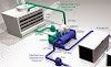
4. Evaporation. The low-pressure liquid absorbs heat from indoor air or water and evaporates to a gas or vapor form. The low-pressure vapor flows to the compressor and the process repeats. As shown in Figure 1.1, the vapor compression refrigeration system consists of four components that perform the four steps of the refrigeration cycle. The compressor raises the pressure of the initially low-pressure refrigerant gas. The
 |
| FIGURE 1.1 Basic components of the vapor compression refrigeration system. Condition point numbers correspond to points on pressure–enthalpy chart (Figure 1.3). |
Refrigeration Machines :
condenser is a heat exchanger that cools the high-pressure gas so that it changes
phase to liquid. The expansion valve controls the pressure ratio, and thus flow
rate, between the high- and low-pressure regions of the system. The evaporator is
a heat exchanger that heats the low-pressure liquid, causing it to change phase
from liquid to vapor (gas).
Thermodynamically, the most common representation of the basic refrigeration
cycle is made utilizing a pressure–enthalpy chart, as shown in Figure 1.2.
For each refrigerant, the phase-change line represents the conditions of pressure
and total heat content (enthalpy) at which it changes from liquid to gas and vice
versa. Thus, each of the steps of the vapor compression cycle can easily be plotted
to demonstrate the actual thermodynamic processes at work, as shown in
Figure 1.3.
Point 1 represents the conditions entering the compressor. Compression of the
gas raises its pressure from P1 to P2. Thus, the “work” that is done by the compressor
adds heat to the refrigerant, raising its temperature and slightly increasing
its heat content. Thus, point 2 represents the condition of the refrigerant leaving
the compressor and entering the condenser. In the condenser, the gas is cooled,
reducing its enthalpy from h2 to h3.
The portion between points 3 and 4 represents the pressure reduction that
occurs in the expansion process. Due to a small percentage of the liquid evaporating
as a result of the pressure reduction, the temperature and enthalpy of the
remaining liquid are also reduced slightly. Point 4 then represents the condition
entering the evaporator. The portion between points 4 and 1 represents the heat
gain by the liquid, increasing its enthalpy from h4 to h1, completed by the phase
change from liquid to gas at point 1.
 |
| Basic refrigerant pressure–enthalpy relationship. |
 |
| Ideal refrigeration cycle imposed over a pressure–enthalpy chart. |
>
For any refrigerant whose properties are known, a pressure–enthalpy chart canbe constructed and the performance of a vapor compression cycle analyzed by
establishing the high and low pressures for the system. (Note that Figure 1.3
represents
an “ideal” cycle and in actual practice there are various departures
dictated by second-law inefficiencies.)
Refrigerants:
Any substance that absorbs heat may be termed as a refrigerant. Secondary
refrigerants, such as water or brine, absorb heat but do not undergo a phase change
in the process. Primary refrigerants, then, are those substances that possess the
chemical, physical, and thermodynamic properties that permit their efficient use
in the typical vapor compression cycle.
In the vapor compression cycle, a refrigerant must satisfy several (sometimes
conflicting) requirements:
1. The refrigerant must be chemically stable in both the liquid and vapor
states.
2. Refrigerants must be nonflammable and have low toxicity.
3. The thermodynamic properties of the refrigerant must meet the temperature
and pressure ranges required for the application.
Refrigeration Machines:
Early refrigerants, developed in the 1920s and 1930s, used in HVAC
applications
were predominately chemical compounds made up of chlorofluorocarbons
(CFCs) such as R-11, R-12, and R-503. While stable and efficient in
the range of temperatures and pressures required within contained HVAC cooling
systems, these CFC refrigerants were also used as aerosol propellants and cleaning
agents in a wide range of industrial and commercial products. Once released into
the air, these refrigerants had significantly adverse effects on the atmosphere.
CFC refrigerant gas was found to be long lived in the atmosphere. In the lower
atmosphere, the CFC molecules absorb infrared radiation and, thus, contribute to
atmospheric warming. Then, once it is in the upper atmosphere, the CFC molecule
breaks down to release chlorine that destroys ozone and, consequently, damages
the atmospheric ozone layer that protects the earth from excess UV radiation.
These, and all other refrigerants, are now assigned an Ozone Depletion Potential
(ODP) and/or Global Warming Potential (GWP), defined as follows:
• ODP of a chemical compound is the relative amount of degradation it
can cause to the ozone layer.
• GWP is a measure of how much a given mass of a gas contributes to
global warming. GWP is a relative scale that compares the greenhouse
gas to carbon dioxide with a GWP, by definition, of 1.
Table 1.1 summarizes the ODP and GWP for a number of refrigerants commonly
used in HVAC chiller systems.
The manufacture of CFC refrigerants in the United States and most other
industrialized nations was eliminated by international agreement in 1996. While
refrigeration equipment that utilizes CFC refrigerants is still in use, no new equipment
using these refrigerants is now available in the United States or Europe.
Earlier on, to replace CFCs, researchers found that by modifying the chemical
compound of CFCs by substituting a hydrogen atom for one or more of the chlorine
or fluorine atoms resulted in a significant reduction in the life of the molecule
and, thus, almost eliminated ODP and significantly reduced GWP. Some of these
compounds, called hydrochlorofluorocarbons (HCFCs), are currently used in
HVAC water chillers, especially R-22 and R-123.
While HCFCs have reduced the potential environmental damage from refrigerants
released into the atmosphere, the potential for damage has not been totally
eliminated. Again, under international agreement, this class of refrigerants is
slated for phaseout for new equipment installations in 2010–2020, with total halt
to manufacturing and importing into the United States mandated by 2030, as
summarized in Table 1.2.
>
To replace HCFCs, a third class of refrigerants, called hydrofluorocarbons
(HFCs), has been developed since about 1990, including R-134a, R-410A, and
R-407C, all of which are commonly applied in HVAC equipment, although the
latter two are primarily used only in smaller-packaged DX systems. This class
of refrigerants has essentially no ODP and GWP levels that are 50–70% lower
than CFCs.
 |
| ODP and CWP for Common Refrigerants |
R-134a is utilized in positive-pressure rotary compressor water chillers offered
by the vast majority of manufacturers. However, at least one manufacturer continues
to offer negative-pressure centrifugal compressor water chillers using R-123
(an HCFC), creating a design dilemma for engineers and owners. At this time,
R-123 chiller has only 8–9 years of guaranteed refrigerant supply and new installations
of chillers using this refrigerant should be avoided.
Unfortunately, HFCs still have fairly high GWPs. Already, in Europe, there is
legislation requiring that these refrigerants be eliminated. The European Union
has issued a directive to phase out refrigerants with a GWP greater (ultimately)
than 150 in autos beginning in 2011. This limitation is expected to be applied to
HVAC systems beginning in 2015.
While no GWP-limiting legislation exists for the United States, there is a search
underway for new low-GWP refrigerants to replace HFCs worldwide. This search is
currently centering around older refrigerants such as R-245a (propane), especially in
Europe, and R-717 (ammonia). Both refrigerants are highly flammable and ammonia
has specific safety concerns and requirements that limit its potential application.
You can find in the blog of air-conditioning all the news and information in the field of cold and climatisaion in club chiller control
https://www.masabihaddoja.com/
airconditioner-auto
http://adf.ly/1OJam9
clubclimfroid.blogspot
http://adf.ly/1OJazt
clubchillercontrol.blogspot
http://adf.ly/1OJb4w
youtubeclimafroid.blogspot
http://adf.ly/1OJbKo
youtube.com/user/abobahaaeddine
http://adf.ly/1OJbQM
kandi younes


0 Comments